Geometric Dimensioning and Tolerancing (GD&T) is a system of symbols, rules, and principles used to define and communicate engineering specifications for product design and manufacturing. It is a crucial aspect of modern engineering and plays an important role in ensuring that products are designed and manufactured to the required specifications.
The primary purpose of GD&T is to provide a precise and unambiguous language that can be used to define the geometry of a part or assembly and the allowable variation or tolerance on that geometry. This is important because traditional methods of specifying dimensions and tolerances can be ambiguous and subject to interpretation, leading to inconsistencies and errors in manufacturing.
GD&T is based on a set of rules and symbols that are used to define the geometry and allowable variation of a part or assembly. The system is based on three main principles: form, orientation, and location. These principles define the shape, size, position, and orientation of features on a part or assembly.
Form refers to the shape or geometry of a feature on a part. It is defined using symbols such as straightness, roundness, cylindricity, and flatness. Orientation refers to the position or angle of a feature relative to a reference datum. It is defined using symbols such as perpendicularity, parallelism, and angularity. Location refers to the position of a feature relative to a reference datum or other features on the part. It is defined using symbols such as position, concentricity, and symmetry.
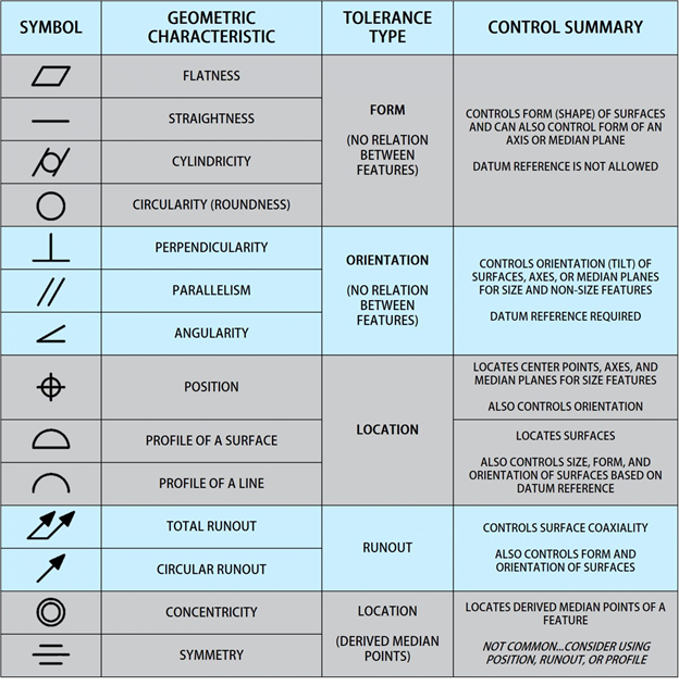
Runout is a category by itself and indicates the accepted amount of a particular feature that can vary compared to the datums.
GD&T symbols define these principles and specify each feature’s allowable variation or tolerance. The symbols are standardized and universally recognized, allowing engineers and manufacturers to communicate specifications clearly and unambiguously.
One of the significant advantages of GD&T is that it allows for tighter tolerances than traditional dimensioning methods. This is because GD&T considers the relationship between features on a part rather than just specifying individual dimensions. Using symbols to define form, orientation, and location, engineers can specify tighter tolerances while ensuring that the part or assembly will function correctly.
GD&T, together with drawings, PFMEAs, work instructions, bubble drawings, inspection plans, FAIRs, and BOMs, has become increasingly important in modern engineering and manufacturing industries due to the increasing complexity of designs and the need for precise and accurate parts.

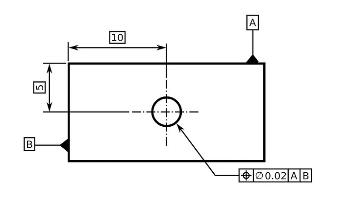
The Feature Control Frame (FCF) controls the features of the design. One feature frame can only carry one message containing the instruction the design must follow.
The symbol in the first box will dictate the Geometric Characteristic of the feature. Each FCF can only represent one Geometric Characteristic, so If the engineer needs to order another Geometric Characteristic in the same feature, it must generate another FCF.
The second space will inform about the Total Tolerance. The Total Tolerance comprises the Shape of the Tolerance Zone, Individual Feature Tolerance, and Feature Modifier.
The third space can contain up to three boxes representing the tridimensional space and withhold the datum feature references. Not all designs require a datum feature. It will only be needed if it is necessary to specify a location tolerance, such as position.
GD&T also has the advantage of being more flexible than traditional dimensioning methods. Because GD&T is based on principles rather than specific dimensions, it allows for more variation in the actual dimensions of a part or assembly. This means that parts can be manufactured with a broader range of tools and processes without sacrificing performance or functionality.
The benefits of using GD&T are numerous. First and foremost, it improves the quality of the parts being manufactured. By specifying exact tolerances and dimensional requirements, GD&T helps to eliminate errors and reduce the number of rejected parts. It also helps to reduce manufacturing costs by streamlining the manufacturing process and reducing the need for rework.
Despite these advantages, GD&T can be complex and challenging to master. The system requires a thorough understanding of geometric principles and the ability to interpret complex drawings and symbols. Training and education are essential for engineers and manufacturers who want to use GD&T effectively.
In conclusion, Geometric Dimensioning and Tolerancing (GD&T) is a powerful tool consisting of a system of symbols, rules, and principles used to define and communicate engineering specifications for product design and manufacturing. It is based on three main principles: form, orientation, and location, and allows for tighter tolerances and greater flexibility than traditional dimensioning methods. While GD&T can be complex and difficult to master, it is an essential aspect of modern engineering. It plays a crucial role in ensuring that products are designed and manufactured to the required specifications.
As professionals, it’s important to have a solid grasp of the principles of GD&T (Geometric Dimensioning and Tolerancing). This knowledge can make all the difference in creating accurate and precise designs. By mastering GD&T, we can ensure that our products meet industry standards and exceed customer expectations. Let’s continue to educate ourselves and enhance our skills in this critical area.
This GD&T Pocket Guide is my everyday consult book when making drawings.
It is easy to use, straight to the point, and enlightening when talking about Geometric Dimensioning and Tolerancing (GD&T)
I do recommend it 100%.

Leave a comment